 |
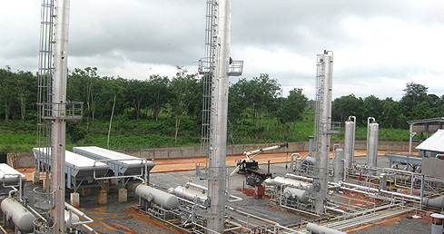
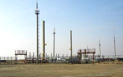
The recovery of light hydrocarbons refers to the removal of ethane, propane, butane and heavier hydrocarbons from the gas stream. Natural gas liquids (NGL) is the general term for liquids extracted from the natural gas stream (ethane and heavier products) and liquefied petroleum gas (LPG) is the term used to refer to extracted liquids where the main components are propane, n-butane and iso-butane. Depending on the requirement, hydrocarbon dew point control packages or cryogenic plants can be used to extract NGL from gas streams. To extract individual components from the NGL, fractionation will typically be required. At SPEC we have a successful track record of providing packaged HCDPC, Cryogenic Plants and LPG extraction and filling plants. |
Hydrocarbon Dew Point Control
Hydrocarbon dew point refers to the temperature at any pressure range or the pressure at any temperature range where hydrocarbons begin to condense from the gas mixture. At the same temperature, heavier hydrocarbons’ dew point temperature increases as the pressure is reduced. Hydrocarbon dew point control (HCDPC) can be used for the extraction of NGL from gas streams. Depending on the product requirements and the gas stream specifications, SPEC provides customized HCDPC packages to meet our customers’ requirements.
Low Temperature Separation Package
Given sufficient pressure, low temperature separation units can be used for HCDPC. Low temperature separation packages work on the principles of the Joule-Thomson effect—that gases cool when expanded at constant enthalpy from higher pressure to a lower pressure. The cooling of the gases causes hydrocarbons to condense.
 |
Process Description
LTS systems require high pressure gas to be a viable form of HCDPC. High pressure gas enters a heat exchanger coil at the bottom of the separator where the gas is cooled. A high pressure separator removes any water or condensate formation caused by the cooling of the gas. The high pressure gas then passes through a reducing valve where the Joule-Thompson expansion occurs. The hydrocarbon liquid drops to the bottom of the separator while the gas leaving has a dew point equal to the temperature and pressure of the separator. Glycol injection can help prevent hydrates in the event that dehydration units have not been installed upstream. |
Process Diagram
Major Equipment
- Low Temperature Separator with integrated heating coil
- High Pressure Separator (HPKO)
- Heat Exchanger
- Expansion Valve
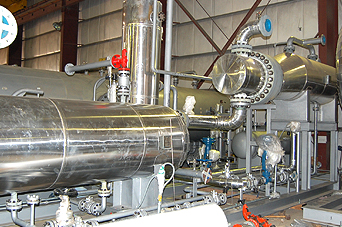
Mechanical Refrigeration Package
When sufficient pressures are not available for LTS, mechanical refrigeration can be used for HCDPC and for the removal of hydrocarbons from the gas.
Process Description
The inlet gas passes through a gas/gas heat exchanger where the gas leaving the cold separator cools the warm incoming gas. The inlet gas then heads to a chiller, typically kettle type shell and tube exchanger using propane as the refrigerant. From the chiller the gas and liquid are separated in a three phase separator: Water and glycol (if it was to prevent hydrate formation), liquid hydrocarbon and gas. The liquid hydrocarbon is sent to distillation towers for separation of the liquid hydrocarbon into its individual components. The top gas is used in the gas/gas heat exchanger and then is an outlet gas from the plant.
Process Diagram
Please insert process diagram
Major Equipment
- Gas/Gas Heat exchanger
- Chiller
- Cold Separator
SPEC experienced engineers can help decide which HCDPC process is appropriate for your application.
Top ^
Cryogenic Plants
When higher recovery of ethane and propane is required than HCDPC packages can attain, cryogenic plants are required. In the gas industry, cryogenic temperature typically refers to temperatures below -45°C. SPEC provides the following methods for achieving cryogenic temperatures:
- Turbo Expanders
- J-T Valve Expansion
J-T Valve Expansion
This process is typically used for smaller gas flows. It is cheaper to install and operate than turbo expander units but will yield lower ethane recovery. This process uses the Joule-Thompson effect for achieving cryogenic temperatures. To achieve the cryogenic temperatures, a high differential pressure is required across the J-T valve along with sufficient heat exchange.
Process Description
The dry gas is typically dried using molecular sieve units to achieve water concentrations below 1 ppm. The dry gas is first cooled with a heat exchanger before being expanded across a J-T valve. After the J-T valve, the liquid is sent to a cold separator where the liquid is sent to the de-methanizer tower while the overhead gas is used to cool the inlet feed gas in the heat exchanger. To increase efficiency and/or compensate for lower gas pressure, mechanical refrigeration can be added.
Advantages
- Modest ethane recovery
- Simple design and operation
- No rotating equipment required
Limitations
- High pressure required
- Cannot achieve ethane recoveries as high as Turbo Expanders
Major Equipments
- Molecular Sieve Dehydrators
- Gas/Gas heat exchanger
- J-T Valve
- Cold Separator
- De-methanizer Tower
- Reboilers
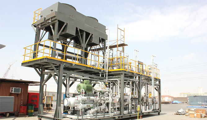
Turbo Expander Process
The use of turbo expanders is the predominate process for the recovery of ethane from gas. Turbo expanders use a turbine to expand the gas to cool the gas down to -101°C, sufficiently lower than a J-T valve alone.
Process Description
Molecular Sieves are used to dry the gas below 1 ppm prior to the turbo expansion process. Depending on the gas composition, a Gas/Gas exchanger is used for initial cooling of the incoming dry gas. If the gas has a richer composition, mechanical refrigeration may be required. The cooled gas is then sent to a cold separator. From the cold separator, a J-T Valve and Turbo expander work in parallel. The J-T Valve handles the bottoms and the top gas heads to the Turbo expander. Both Liquids are then sent to a De-methanizer tower for the removal of methane at the top and NGL at the bottom.
Process Diagram
Please insert Process Diagram
Major Equipments
- Gas/Gas Exchanger
- Cold Separator
- J-T Valve
- Turbo Expander
- De-methanizer Tower
Top ^
Liquefied Petroleum Gas
Fractionation
The fractionation process is used to separate the bulk natural gas liquid into component products: ethane, propane, butane and natural gasoline (C5+) or any combination of these. A series of fractionation towers exploit the relative volatility of the individual products for separation. SPEC engineers design the process to ensure the final products match our customers’ requirements.
Process Description
Heat is introduced at the bottom of the tower which causes the more volatile components to be driven to the top of the vessel. Simultaneously, liquid reflux enters from the top of the fractionation tower driving the less volatile components to the bottom of the tower. |
|
Trays installed within the tower ensure that the vapor and liquid phases are continuously in contact allowing for the desired separation. As a result, the less volatile product has been isolated (will not be 100% pure but will be within the acceptable limits). The first product to be removed is ethane followed by propane, butane and finally natural gasoline. Depending on the degree of separation sought will determine the number of towers that are required.
Major Equipment List
- Fractionation Towers (trays installed)
- De-ethanizer Tower
- De-propanizer Tower
- De-butanizer Tower
- Reboilers
- De-ethanizer Reboiler
- De-propanizer Reboiler
- De-butanizer Reboiler
- De-ethanizer Overhead Condenser
- Reflux Accumulators
- Reflux Pump
|