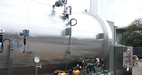

Water Bath Heater
| Water bath heaters have an established history of successful application in the oil and gas industry. They are used in a variety of operations; from heating of natural gas to the heating of crude. Water bath heaters are commonly used in applications where the required outlet process temperature does not exceed 87 ˚C. |
The primary applications for Water Bath Heaters include:
• Heating Natural gas prior to pressure reduction manifolds to prevent freezing of expansion valve
• Hydrate prevention
• Heating of process fluid upstream of separation units to enhance separation efficiency
• Heating of crude oil to maintain temperature above the paraffin pour point
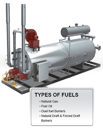
The heater consists of three main components: the shell, the firetube, and the process coil. These components are
carefully designed for each standard size as well as for our customized packages.
HEATER SHELL
The heater shell is fabricated of Carbon Steel, with two saddletype supports. The heater shell is the basic vessel into which
the firetube and coil are assembled. It holds the water bath which surrounds both the firebox and, coil. The flow coil and
firebox are inserted into the shell from opposite ends.
THE FIRETUBE The firetube normally consists of single or multiple “U”-shaped firetubes fabricated from heavy-wall pipe. When assembled,
THE PROCESS COIL The Process coil is the only portion of the heater that operates under more than atmospheric pressure. The Process coils are fabricated from seamless pipe and in accordance with ASME Section VIII, Div 1. The Process coils are attached to their flange plate so that the entire coil is above the firetube. This places the coil in the hottest portion of the water bath, thereby assuring rapid and efficient heat transfer. To ensure the highest level safety and integrity, the process coils are 100% radiographed. |
 |
PROCESS DESCRIPTION
Fuel (Fuel Gas or Fuel Oil) is burned within the horizontal “U”-shaped firebox immersed in the lower portion of the water bath.
Heat released by the burning fuel is quickly transmitted through the firetube wall to the water bath, maintaining it at the desired
temperature.
The fluid to be heated (wellstream, natural gas, oil, water, etc.) flwos through the process coil of the heater which is immersed in the upper portion of the water bath. Heat is transmitted from the hot water bath through the tube-wall to the fluid inside the process coil.
The heater temperature controller maintains the water bath temperature at the desired level by controlling the firebox fuel gas supply. A temperature of 87 ˚C is considered the maximum temperature for operation. It is preferred to operate the heaters less than 87 ˚C when inlet condition and/or outlet temperature requirements allow.
Operating the bath temperature at the minimum temperature required to give hydrate protection in either the pipeline or separator not only saves fuel, but provides maximum liquid recovery in the downstream equipment.
STANDARD COMPONENTS AND ACCESSORIES:
• Removable “U”- bend type firebox w/cover plate
• Flue Gas Stack with rain cap and bird screen
• Removable process flow coil w/cover plate.
• Fuel gas preheat coil
• High efficiency burner with BMS
• Fuel gas manifold
• Level Gauge
• Temperature Gauge
• Top Mounted Expansion Vessel with thief hatch
• Electropnuematic Instrumentation including:
- Low Level Switch
- High Temperature Switch Mounted on Flue Stack
- Temperature Controller (Transmitter or Pneumatic)
- Low Pressure Switch for Fuel gas
• Fill Connection
• Two Coat Paint System
SPEC specializes in custom packages and can engineer the systems to meet client specifications and requirements.