Equipment
The filter/coalescer section removes solids and coalesces fine liquid aerosols into larger droplets. A vane section then removes the coalesced liquid.

Gas Lift Compression Station Skids for Tonmoor Jones Creek, Nigeria 2019
ScopeTwo gas filter separator skids, with the station's scrubber, drain vessel and injection manifold skids.
Application
Entrained liquid aerosols (compressor lube oils, trace hydrocarbons and water mist) have to be removed from natural gas streams to protect downstream equipment. An effective coalescing separator and media combination prevents costly problems and downtime on compressors, membranes, instrument valves and piping.
Process
The coalescer filter section removes bulk liquid and solid particles, and coalesces fine liquid droplets into larger ones. Those larger droplets are then removed in a second double pocket (DP) vane section. SPEC uses high capacity DP vanes to increase throughput and so minimise the separator diameter.
In the horizontal double barrel configuration, gas flow is maximised in the upper barrel without re-entrainment while the liquid drops into the lower barrel. Coalescing filters are offered either as standard elements replaced periodically, or as designs that can be cleaned and reused.
System configuration
System configuration varies with process duty, operating conditions and project requirements.
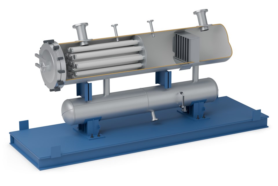
Filter elements remove solids and bulk liquid and coalesce fine droplets into larger ones.
High-capacity vanes remove the coalesced droplets from the gas, which keeps the separator diameter down.
In the horizontal double barrel design, liquid drops into the lower barrel while the gas flows through the upper one.
Gives straightforward access for filter element change-out.
Let the vessel drain completely for inspection, cleaning and element change-out.
Final equipment arrangement and delivery format depend on process duty, transport constraints and site requirements.
Orientation
| Configuration | Characteristics |
|---|---|
| Horizontal double barrel | Gas flow maximised in the upper barrel without re-entrainment; liquid drops into the lower barrel |
| Vertical | Uses gravity to remove liquid; only the lower portion of the element saturates; more flow-through for a given housing size, allowing smaller and less expensive hardware at the same flow rate |
Specifications
| Parameter | Value |
|---|---|
| Design code | ASME Pressure Vessel Code, Section VIII, Division 1 |
| Standard design pressure | 1440 psi (99 bar) |
| Design temperature (stock vessels) | −20 °F to 130 °F (−29 °C to 54 °C) |
| Access | Quick open closure for straightforward filter element change-out |
| Drainage | Element support plate and bottom drains completely drain the vessel for inspection, cleaning and element change-outs |
Non-stock design pressures and temperatures are engineered to your process conditions.
Placement
| Position | Duty |
|---|---|
| Ahead of compressors | Removes water and oil mist and dust that would damage valves and cylinders |
| Ahead of desiccant dehydrators | Prevents lube oil mist and other liquid contaminants entering the absorbent bed and degrading the desiccant |
| Ahead of glycol dehydrators | Removes compressor lube oil mist to prevent contamination or foaming of the glycol |
| After compressors | Removes lubricating oil mist from the discharge stream |
| After contactors | Removes glycol or amine carryover downstream |
Advantages
High capacity DP vanes raise throughput, which keeps the separator diameter down.
No plugging of the DP vane, and quick open closures for fast element change-out.
High separation efficiency often allows more throughput from equipment already installed.
Evidence
For Tonmoor International's Jones Creek gas lift compression station in Nigeria, SPEC designed, fabricated and tested two gas filter separator skids, together with the station's scrubber, drain vessel and injection manifold skids.
Detail
The quick opening closure, element support plate and vane section are sized together from the gas rate and the contaminant load. Vessels are fabricated, radiographed and hydrotested in SPEC facilities before the unit is completed and shipped.
Related
Vertical and horizontal separators for wellhead and inlet duty.
View →Separating liquids of different densities where no emulsion exists.
View →One of the units a filter separator is installed to protect.
View →Process data

Enquiries
Send us your process data and operating conditions, and we will review the duty with you.
Contact Us